GD427 MK IV

GD427 MK IV
What my car should look like when finished - Stoneleigh 2015

Sunday 11 December 2016

Heater Pipes - Continued

After making up wooden clamps and the use of duct tape, I made up stainless steel brackets for the heater pipes which go from the water pump at the driver's side across the car to the passenger's side.


I had a friend come over to TIG weld the brackets to the stainless pipes for me.  I then used some pickling paste to clean the weld after.

This then enabled me to finally bolt up the cross brace to the chassis.  I just have to install the 90 degree hoses and also the heater valve.


Wednesday 30 November 2016

Fuel System

I finally decided on the fuel system for the car.  I decided on using Aeromotive equipment and to utilise their in-tank Phantom system.  The fuel tank will require some modification though....

I have bought Goodridge 811 PTFE lined Stainless steel braid with fittings to go along with it.

I will post updates once I start installing it all.


Monday 28 November 2016

Jacking Point

As mentioned in a previous post (here), I made ready the chassis to accept a jacking point.  I tried my skills at 3D drawing using Solidworks and I managed to sketch what I wanted made including dimensions.  I then had a local company manufacture the unit from stainless steel.


It looks to be a good solid install and a good idea from Larry at Club GD.

Wednesday 16 November 2016

Heater Pipes

I decided to install my own heater pipes as opposed to the ones supplied since I wanted to minimize rubber hoses and coupling joints.

I used some 18mm O/D stainless steel tube with a 90 degree bend turning towards the engine.  I have used some MDF with 18mm holes to line up the pipes to allow bracket design.  I will have to fabricate some stainless brackets to bolt to the cross brace under the windscreen washer tank and also to weld to the stainless pipes.

I will then attach this to the engine with 90 degree silicone elbows.

I spoke with a mechanic and asked him if he knew of any electronic heater controllers available.  He suggested a Ford Kuga valve.

I bought one and modified it to line up with the 18mm heater pipes.  I am waiting on silicone hose to connect up the heater controller.  The valve is controlled by using a variable voltage which I will add at some point controllable from the dashboard.  I will have to add some more wiring to the loom to connect this up.

Keep checking my blog for updates....

Note: The photo shows the cross brace / heater pipes assembly upside down.


Wednesday 9 November 2016

Rollin', Rollin', Rollin'

Since the exhaust has been clamped up and the majority of the chassis work is now done, I decided to lower the chassis to the ground.

I used two engine cranes and two lifting strops to lift the chassis up enough to remove the trestles.  I then slowly lowered the chassis to the ground.  It rolls!

The only issue I have now is that the right rear tyre has a slow puncture.....  I'll have to see if I can find some other wheels / tyres.......


Tuesday 8 November 2016

Sensored!

I decided to over complicate my Oil Pressure & Oil / Water Temperature sensors for the gauges.  I thought it would be a good idea to have the possibility of having the measurements input to a data logger of some kind.  I opted to buy sensors from GM that have dual circuitry.

They have 3 pins.  One pin is for the gauge, and the other two pins are for a 5V signal into an ECU / Data Logger.  I thought that this would future proof my install in case I wanted to add the data logging function.

After surfing the net for a while, I discovered that the correct part numbers were:

Oil / Water Temperature Sensor (3-Wire):  GM#  12551708
Oil Pressure (3-Wire):  GM#  12616646

These have the correct threads / sealing washer to be able to screw straight into the LS engine without any adapters.

I found out (I haven't verified this myself) that these sensors are of US 280F range, so I'm assuming a gauge won't be an issue.........

Also, I bought the 3-pin connectors from Simtek UK (CON-323):  Direct Link

I need to put some extra wiring into the loom to accommodate the sensors, and I will post when that is done.

I had to drill and tap the housing above the oil filter since this was blanked off.  This was done by removing it from the engine, drilling and tapping it to M12 x 1.5mm (Not a standard M12 thread).  This was fully cleaned from debris before bolting back together.

I hope they work.......


Tuesday 25 October 2016

Exhaust Completion & Jacking Point

After dry fitting the exhaust, and marking each part where it should sit, I managed to fit the rear mounting using the reinforced rubber supplied by GD.  I replaced the steel exhaust clamps with stainless steel ones.


While I was fitting the exhaust, I was conscious about what a ClubGD member - Larry, recommended about a rear jacking point to aid lifting the car once complete.

I studied his write up in the club magazine and decided to make up the same idea.

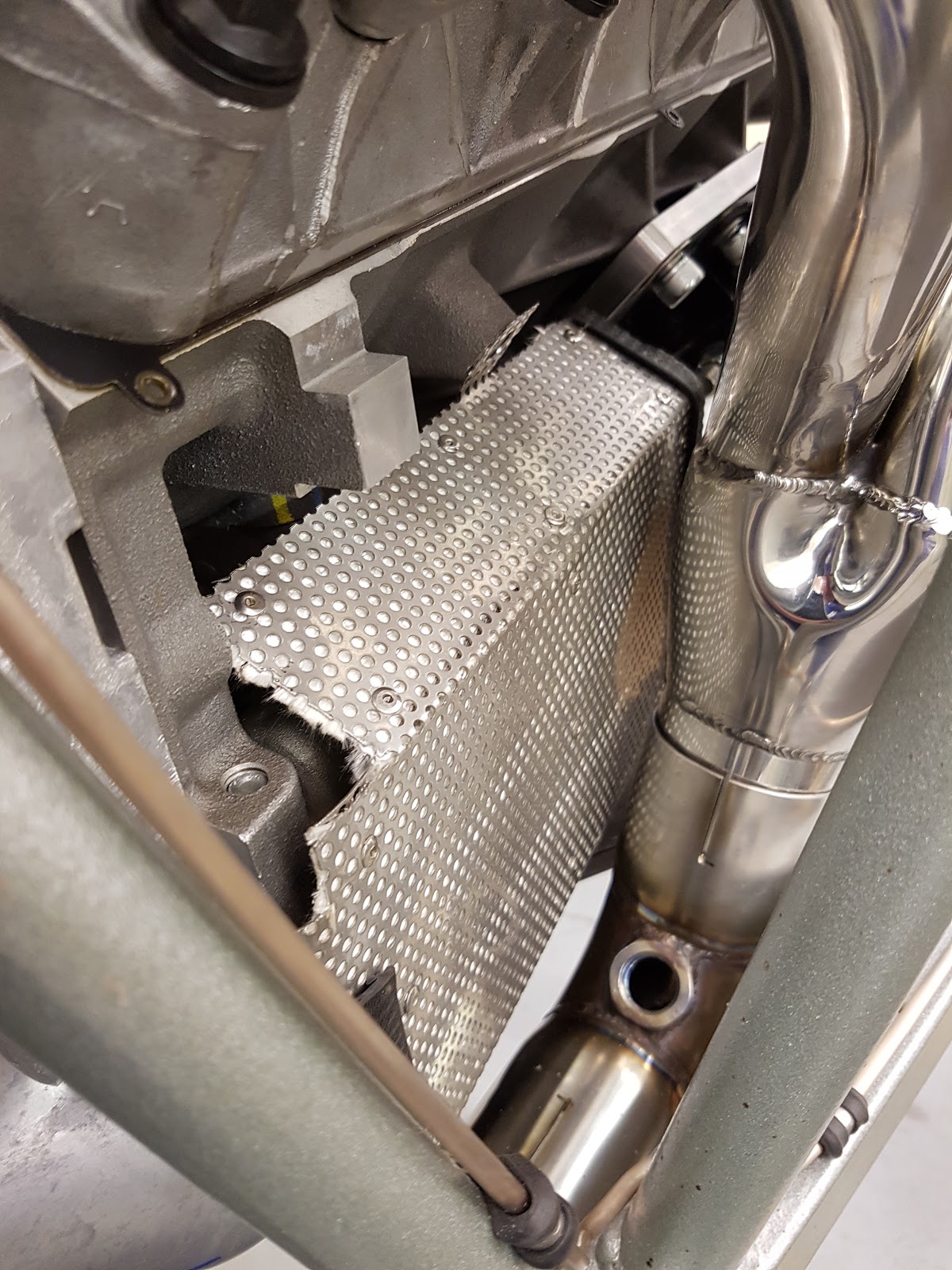
The only issue I had was that on the rear part of the X-pipe was a welded support fouling where the jacking point would go.


With the rear U-bolts clamp being so robust, I felt that the welded in part wasn't too crucial so I cut it out!  This then opened up an area below the rear chassis rail for the jacking point.

I designed a piece of stainless plate - 6mm x 458mm x 83mm, with a short piece (88mm) of 2 1/2" stainless pipe for centering the jack.

I made a template from the design and marked and fitted 6x M8 rivnuts to the underside of the chassis.


I will post another photo once I have made the plate and fitted it.  I then have to make a fitting to link the jacking point to the jack.....

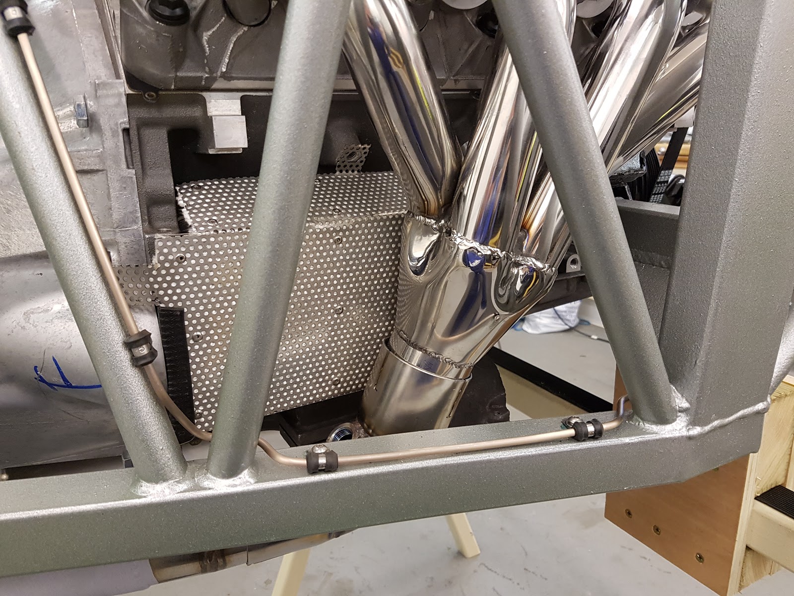
I then proceeded to finally assemble the exhaust using some Catalytic Converter & Sensor Safe RTV sealer (Granville).


I clamped up the exhaust with stainless steel clamps (INOX) to my pre-made markings and it all seems to fit well.

Friday 21 October 2016

Four wheels!

I managed to find some wheel nuts that I bought for an old Honda that I owned.  They are the correct thread - M12x1.5mm.  I now have four wheels fitted with 2 wheel nuts each.  That will be fine for its purpose or moving it around the garage.  It's not as if I will be test driving it....................far!


Thursday 20 October 2016

Two Wheels on my Wagon!

One of my friends owns an old Ford Granada, and I thought he would be worth a try to see if he had any spare wheels.  He had some from a Granada Scorpio.  Exactly what I need!

He had 4 wheels, however he couldn't find any wheel nuts.  I managed to find 4, and so I fitted 2 wheels with 2 nuts each.  I'll have to source some more......


Once the exhaust has been finally fitted, and the other 2 wheels fitted, I will lower the "rolling" chassis to the ground.

Bracing

After fitting the cooling and heater pipes, I decided to fit the 2 front cross braces.  These just needed a few taps to fit, and then bolted up using the high tensile cap head bolts.


A fairly straight forward job!

Heating & Cooling System

I managed to find some time to work on the car during my time off which has moved on quite a bit.  The weather has been excellent for October, and a lot of outside jobs have also been done which took priority.

I re-fitted the radiator which I had previously fitted the fan brackets and fan.  I cut some rubber hose for the top mount.

After initially receiving the incorrect radiator tank (I have a newer LS water pump), I have finally manged to fit it to the upper cross brace.  I set the tank on the cross brace and lined it up to the water pump using the 38mm to 32mm silicon hose.  I then marked and drilled the underside of the brace and tapped the hole to M6 and bolted it up.


I temporarily installed the air inlet pipe to be able to align the windscreen washer tank.  I checked the overhang of the bodyshell to ensure that the tank wouldn't foul, and decided that I would make the centres of the caps at even distances from the air inlet.


I ordered the stainless pack from GD for the heater matrix and also for the lower radiator hose.  The 2 x 16mm pipes have brackets pre-welded onto them for fitment on the upper cross brace.  I had to remove some of the tank brackets to permit fitment, and I used M5 button heads to fix it.


 I also used the CNC machined thermostat housing supplied by GD which I finally bolted up in the orientation that seemed to fit best.


I need to order more stainless clamps to finally fit the hoses and finally bolt in the upper cross brace.  I still require to order some 16mm hose for the heater, and figure out the final position of the heater matrix.


Exhausting!

I managed to source some help in dry fitting the exhaust to ensure correct alignment.  This took a bit of maneuvering but I think it is now in a position that it is ready for final sealing and clamping.  I bought some stainless clamps (Similar to Mikalor) which will keep the exhaust system rust free and less likely to hit the ground when driving.

I have marked each joint with permanent marker so that I can disassemble, apply sealer, and reassemble in the correct location.

I have started making the rear rubber mount, and just need to make the final 3 holes to bolt it to the exhaust hanger.

Once I have finally fitted the exhaust, I plan to lower the chassis to the ground onto some build wheels!


Sunday 2 October 2016

Nuts, Bolts & Washers

With many things to do around the house, and painting windows etc. the car progress has suffered a bit.  I am still scouring the web regarding power steering requirements and some more wiring required.

In the meantime, I finally bought some wall organisers for holding all the A4 stainless set screws, nuts, washers that I had been keeping in plastic compartment boxes.  I bought 3 different types - a 60 drawer, 48 drawer and a 24 drawer.  There is room for one more organiser which I will buy later once I know what size will be the best.


Monday 26 September 2016

Dipstick!

Since my LS7 has been converted to a wet sump system, I require a dipstick.  The engine was built using a batwing sump, and the block had been pre-drilled for the dipstick tube.

After searching for a while on the internet, I found the following information from here.

The Dipstick Tube part number should be 12562360 & the Dipstick 12562468.

However, these part numbers have been discontinued and after speaking with Pace Performance, I deduced that the part numbers that I require are:

Dipstick Tube:    12563817
Dipstick:             12574889

I ordered them from the US and promptly fitted them.  I'll have to see how it lines up once the rocker covers are in place, but I think it is not too far off.  I may get a new handle to get rid of the bright yellow one!

Also, once I drain the current level of oil out (added just for preservation), I will fill the sump with the required amount (6.5 qts.) and check the level on the dipstick to confirm this is indeed the correct one!

I have notched a little piece out of the heat shield, but I will remove approx 5mm more before adding some edging strip to clean up the install.


Monday 12 September 2016

Starter Heat Shield

Since fitting the starter and the exhaust manifold, it was plain to see that the starter requirs a heat shield of some sorts.  There is only 17mm of clearance between the two.

I made a cardboard template out of a Shreddies box and then fabricated a heat shield out of 2 pieces of perforated stainless steel sheet sandwiching some fibreglass tape.  This will hopefully help the starter from getting too hot.

I have bought a dipstick so I will have to cut out a section to allow clearance once I fit it.


Friday 9 September 2016

Exhaust Dry Fit

Apologies for not posting sooner, things have been busy with outside work and I haven't had much time in the garage.

I dry assembled the exhaust to see how it fits and also to mark where the central mounting bobbin requires to be drilled to the gearbox mount.  I pushed all the components together and it seems to fit!  I marked the bobbin and drilled the mount in situ.  I may have to rotate the cats slightly to make a bit more clearance from the chassis.  I will do this just before applying sealer and the stainless clamps.  I also need to drill the rear rubber mount to fix to the chassis.